Guitar Pedal Power Supply: Voltage, Current, Polarity & Isolation Explained
A guitar pedal power supply looks simple until one pedal says 9V 20 mA, another says 9V 500 mA, a vintage unit uses center-positive power, and somebody on a forum says daisy chaining “kills tone.”
The useful way through the confusion is to separate four electrical questions: voltage, current capacity, polarity, and isolation. Get the first three wrong and a pedal may fail to power up or, in the worst case, be damaged. Get isolation wrong and the board may still work, but you can end up chasing hum, digital noise, or ground interactions that disappear with a better power architecture.
Match voltage and polarity; provide at least enough current
Isolation is the fourth question: not usually “will it turn on?”, but “will several pedals share power without creating an avoidable noise problem?”
Voltage: the number you do not improvise with
Voltage is the electrical potential the pedal is designed around. If the pedal specifies 9V DC, use a 9V DC output unless the manufacturer explicitly says the circuit can also accept another voltage such as 12V or 18V.
Feeding a pedal more voltage than it is rated for is not the same as offering it more current capacity. Excess voltage can overstress components. Some overdrives deliberately support higher voltage for increased headroom; many pedals do not. The label or manual wins, not a general rule.
Normally safe
Pedal requires 9V DC; supply output is regulated 9V DC with the correct polarity and enough current capacity.
Do not assume
Pedal requires 9V DC; supply is set to 12V or 18V because “higher voltage sounds better.” Only do this when the manufacturer explicitly allows it.
Truetone’s current power FAQ makes the same point: match the pedal’s voltage requirement and do not substitute 12V, 18V, or AC unless the pedal is specified for it. See Truetone’s power basics.
Current: why a 500 mA output can power a 100 mA pedal
Current is where many pedalboard myths start. A power output marked 500 mA does not force 500 mA through every pedal connected to it. It means the supply can provide up to that amount while maintaining its rated voltage.
A pedal that draws 100 mA on a suitable 9V output will take roughly what its circuit requires. The important requirement is that the output’s capacity is at least what the pedal needs.
Example: 100 mA pedal on a 500 mA 9V output → normal use
Strymon’s power guidance explicitly addresses this common question and notes that voltage, current draw, and polarity are the three basic specifications to check. See Strymon’s pedal power guide.
Problems appear in the opposite direction. If a digital pedal can draw 300 mA and the output is rated for only 100 mA, the pedal may fail to boot, reset, behave unpredictably, or drag the rail outside its intended operating range.
Polarity: center negative vs center positive
Most modern guitar pedals use a barrel connector with center-negative polarity, but “most” is not “all.” Vintage designs, certain specialty pedals, and some legacy devices use different polarity or connector standards.
The polarity symbol near the DC jack shows whether the center pin is negative or positive. Match it exactly. A reverse-polarity adapter changes the connector relationship; it does not change the supply voltage.
Two plugs can physically fit the same jack while being electrically incompatible.
AC vs DC: the label matters more than the plug
Most pedals are powered by DC. Some legacy digital units and specialized devices require AC. The connector can look familiar even when the electrical supply is completely different.
Do not connect an AC output to a DC-only pedal. Do not connect a DC output to an AC-only device and expect polarity adapters to solve it. AC/DC is a separate requirement from voltage and current.
What isolated pedal power supply outputs actually mean
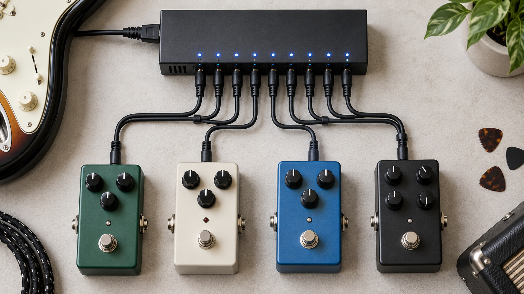
An isolated output is electrically separated from the other outputs rather than simply being another socket on one common supply rail. In pedalboard terms, that separation reduces shared-ground interactions and prevents one pedal from easily injecting switching noise into every other pedal through the power connection.
Isolation is especially valuable when a board combines high-current digital pedals, analog gain stages, pedals in an amplifier effects loop, and multiple audio-ground paths. It is not magic noise removal; poor cables, bad shielding, high-gain hiss, single-coil hum, and ground problems elsewhere still exist.
Daisy chains: when they work perfectly — and when they do not
A daisy chain is not automatically bad. Several low-current analog pedals with the same voltage and polarity can often share a suitable supply with no audible problem. If the total current draw stays within the adapter’s capacity and the board is quiet, there is no engineering prize for making it more complicated.
The risk rises when you mix noisy digital switching circuits with sensitive analog gain pedals, connect pedals to different grounding environments, or approach the current limit of the shared supply.
Good daisy-chain candidate
A few conventional 9V analog drives with low current draw, same polarity, short board, no noise symptoms.
Better isolated
High-current digital delay/reverb/modeling pedals mixed with high-gain analog stages, complex loop routing, or a board already showing whine/hum.
If you are still planning the physical board, our guitar pedalboard setup guide covers signal-chain structure, while the pedalboard guide handles the platform itself.
Digital pedals: current draw, startup behavior and why “it almost works” is not good enough
Modern digital pedals can draw several hundred milliamps and may have higher demand during startup than a simple analog drive. An under-capacity output can produce symptoms that look like software bugs: boot loops, random resets, clicks, frozen displays, or the pedal simply refusing to start.
Always use the manufacturer’s stated requirement rather than guessing from the pedal’s size. A tiny digital pedal can draw more current than several large analog pedals combined.
This matters directly in modern time-based rigs. Pedals such as reverb and delay units often sit next to analog gain stages, so a mixed board benefits from planning power as a system rather than counting only the number of sockets.
Voltage doublers and current doublers: useful tools, easy to misunderstand
Special cables can combine compatible isolated outputs, but only when the power-supply manufacturer supports that use.
Do not improvise these combinations with generic splitters. Isolation, phase, connector wiring, and the supply’s internal design matter.
How to design a power plan for a real pedalboard
Make the power map before buying the supply. A spreadsheet is overkill for four pedals but completely reasonable once the board has mixed voltages and high-current digital devices.
| Pedal | Voltage | AC/DC | Polarity | Current requirement | Assigned output |
|---|---|---|---|---|---|
| Drive 1 | 9V | DC | Center negative | Low | Output 1 |
| Digital delay | 9V | DC | Center negative | High | High-current isolated output |
| Reverb | 9V | DC | Center negative | Medium/high | Isolated output |
| Legacy pedal | Check manual | Check | Check | Check | Do not assume |
Leave current headroom and at least one spare output if you expect the board to grow. Buying exactly enough capacity for today often means replacing the supply when one high-current pedal arrives later.
Troubleshooting a noisy pedalboard: prove the power problem before buying new hardware
Noise troubleshooting works faster when you remove variables instead of changing five things at once.
- Run the guitar straight into the amp. Establish the noise floor without the board.
- Add pedals one at a time. Find the point where the unwanted noise appears.
- Power the suspect pedal from its known-good recommended adapter if available. If the noise disappears, shared power becomes a stronger suspect.
- Separate digital and analog pedals onto isolated outputs. Listen again.
- Check audio cables and physical proximity to mains supplies. A power supply cannot fix a bad patch cable.
- Identify the type of noise. Broadband high-gain hiss, 50/60 Hz hum, digital whine, and single-coil pickup hum have different causes.
A guitar noise gate can mute or reduce noise between notes, but it should not be used to hide a preventable power problem. Fix the source first, then gate what remains.
Guitar pedal power supply FAQ
Can I use a 500 mA supply for a 100 mA pedal?
Yes, if voltage, AC/DC type, connector and polarity are correct. The 500 mA figure is available capacity, not current forced through the pedal.
Can I power a 9V pedal with 12V or 18V?
Only when the pedal manufacturer explicitly says that voltage is supported. Higher voltage can damage a pedal that is designed only for 9V.
Do isolated power supplies sound better?
Not automatically. Isolation mainly prevents shared-power interactions and ground-related noise paths. A quiet simple board may sound identical on a good daisy chain.
Why does my digital pedal work on one output but not another?
The outputs may have different current capacities or voltage settings. Check the pedal’s current requirement and the rating of the specific output.
Can a noise gate fix a noisy power supply?
It can hide noise when you are not playing, but it does not remove the noise source and cannot clean noise that is present under sustained notes.
For the broader signal-chain picture, see guitar pedals for beginners. If your board is already high gain, the overdrive vs distortion vs fuzz guide helps separate gain behavior from power-related noise.
How this guide was built: electrical guidance is cross-checked against current Truetone and Strymon power documentation. Always follow the individual pedal and power-supply manuals when their requirements differ from general pedalboard conventions.